A while ago I became interested in building an HF antenna that was not only stealthy but also easily portable. It should not stand out in my covenant controlled neighborhood and should allow easy portable operation at temporary locations. The question was what kind of portable antenna would be easy to set up and how efficient would it be.
I decided to build and compare a vertical magnetic loop with a vertical Hamstick dipole on 20 meters. The reason both are vertical is because they will produce a low angle of radiation when erected only a few feet above ground. If they were mounted horizontally, then they would have to be at least 1/2 wavelength high to produce a low angle of radiation. On 20 meters this would equate to 32 ft above ground. At this height, it is hard to remain stealthy.
The following describes the two antennas, how they were tested and how they compared.
The Magnetic Loop
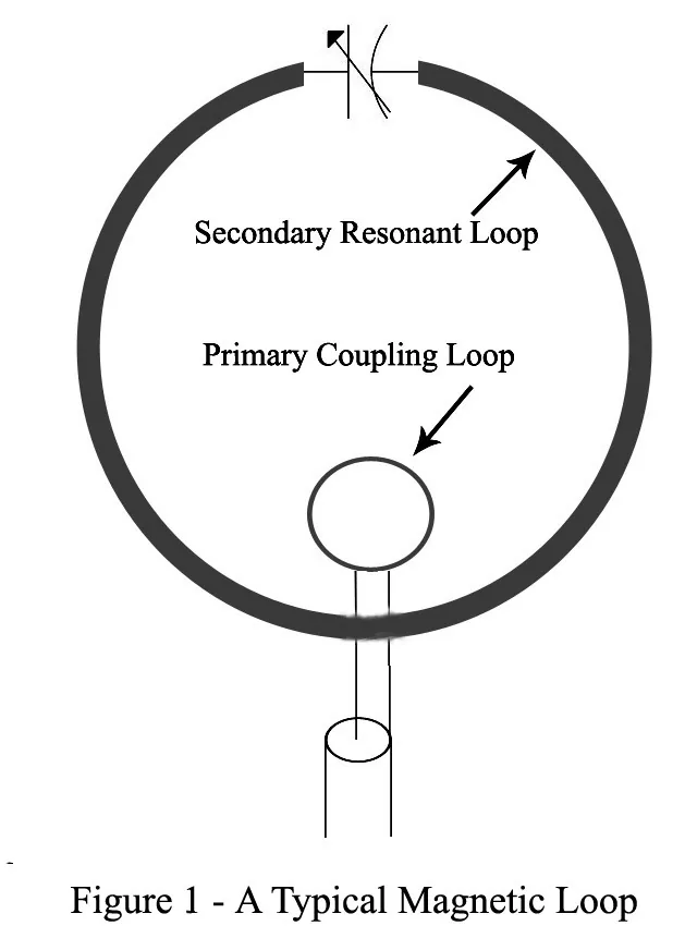
Drawing: Bill Rinker, W6OAV
Figure 1 shows the configuration of a typical magnetic loop antenna. Magnetic loops have been very popular for years in many countries and are becoming very popular in the United States. The reason is because more hams are moving to covenant controlled areas which do not allow antennas or into condos or townhomes where installing outside antennas is an issue.
I chose a magnetic loop because of the following features which make magnetic loops popular:
- Relatively stealthy.
- Multiband.
- Usually smaller in circumference than a quarter wavelength at the highest operating frequency.
- Very close to the efficiency of a high dipole.
- Do not require radials.
- Can be operated very close to the ground when mounted vertically.
- Very low receive noise.
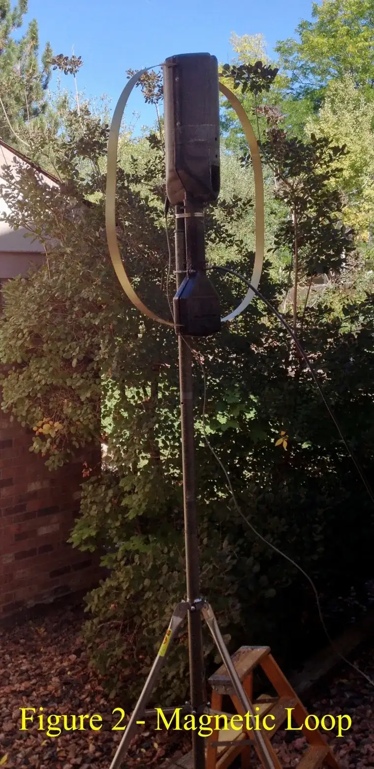
Figure 2 shows my portable magnetic loop. The loop is supported by a fiberglass pole which is in turn supported by a roof mount tripod.
The Hamstick Dipole
I chose to build a vertical dipole out of two Hamstick mobile whips because they are light weight, inexpensive and relatively invisible compared to other whips.
Two versions of Hamstick vertical dipoles were tested. The first was a center fed dipole and the second was an end fed dipole.
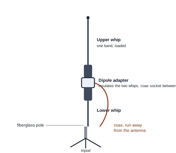
The center fed dipole consisted of two whips mounted on a dipole adapter. This adapter isolates the whips and provides a coax connector between them for the center feed. The adapter is in turn mounted to a fiberglass pole. The pole is supported by a roof mount tripod. See Figure 3.
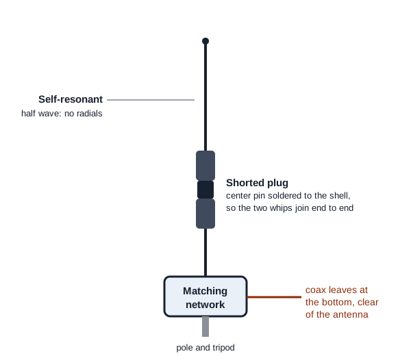
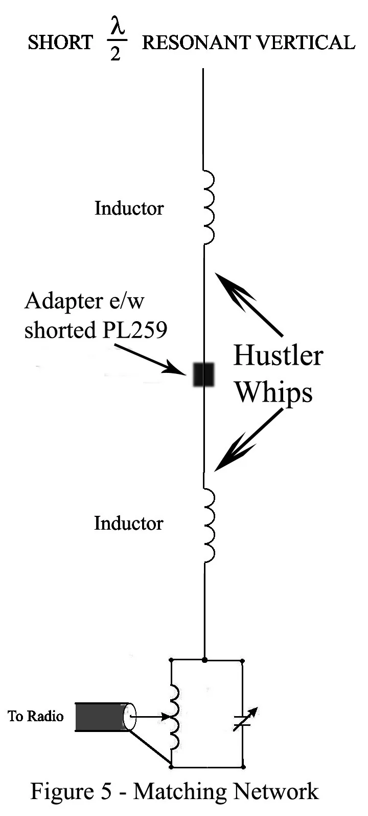
The center fed dipole was converted to an end fed dipole by removing the coax from the dipole adapter and replacing it with a PL-259 with the center conductor shorted to the shell. The shorted PL-259 electrically connected the whips. The tip of the bottom whip was connected to a matching network. See Figure 4. This arrangement eliminated the issue of having to run the coax horizontally for some distance from the vertical to avoid interaction between the coax and the antenna.
Drawing: Bill Rinker, W6OAV
The matching network contained a tapped parallel matching circuit, shown in Figure 5. This is the same matching network used to match full length 1/2 wavelength verticals. The advantage of this vertical dipole is that, unlike a 1/4 wavelength vertical, it does not require radials as it is a self resonant antenna.
Comparison Test
The test consisted of comparing the performance of the two portable antennas to that of a reference antenna. The reference antenna was a 23 ft wire vertical, base tuned with an auto tuner, set on a 35 ft by 4 ft chicken wire ground plane hidden under rocks.
The first test involved comparing the magnetic loop with the reference vertical on 20 meters over a period of a week. During each of the many contacts, the transceiver was switched between the reference vertical and the magnetic loop. The far station was asked to note the peaks of the transmitted signal strength from each antenna. When the far station transmitted, the peak receive S meter readings on both antennas were recorded. In most cases, the magnetic loop heard better and was heard better by the far station. Occasionally signals were equal on both antennas. One thing stood out: the signal to noise ratio was much better on the magnetic loop. Very weak signals were copyable on the magnetic loop but not on the reference vertical.
Next, the center fed vertical dipole was mounted exactly in place of the magnetic loop. This placement ensured that the surrounding environment would equally affect the antennas’ patterns. Again over a week, comparisons, as described above, were made on 20 meters between the reference vertical and the vertical dipole. Most of the time the vertical dipole was about the same as the reference vertical on transmit and receive. The signal to noise ratio was about the same. The tests were repeated with the end fed dipole. Both the center fed and the end fed verticals performed the same.
Conclusion
The comparison test wasn’t very scientific but did give a decent evaluation of the antennas. Both antennas make excellent portable stealth antennas. I did work a couple of DX stations on both antennas using 100 watts when 20 meters was marginal at best. The pros and cons of the antennas are shown below.
| Magnetic loop | Vertical dipole | |
|---|---|---|
| Efficiency compared to a high dipole | Nearly equal | Less |
| Signal to noise ratio compared to a high dipole | Better | Worse |
| Bandwidth compared to a high dipole | Much narrower | Less |
| Ease of setup | Somewhat awkward | Easy |
| Multiband? | Yes, with remote tuning | No, the whips must be changed |
| Cost | Expensive to buy | Inexpensive |
| Weight | Somewhat heavy, and top heavy | Light |
Commercial magnetic loops are expensive, but they can be built inexpensively.