The Question
Replacing a 1/4 wavelength vertical antenna with a longer 5/8 wavelength vertical antenna increases the signal gain towards the horizon. However, I understand that lengthening a vertical antenna beyond 5/8 wavelength is detrimental to signal gain towards the horizon. If this is true, then how do commercial dual band verticals longer than 5/8 wavelength develop signal gain towards the horizon?
The Answer
This response will discuss what happens when a 5/8 wavelength vertical antenna is lengthened, the categories of commercial dual band antennas, how commercial dual band antennas physically longer than 5/8 wavelength increase gain towards the horizon, and how to analyze antenna gain figures.
5/8 versus 3/4 Wavelength Vertical Antennas
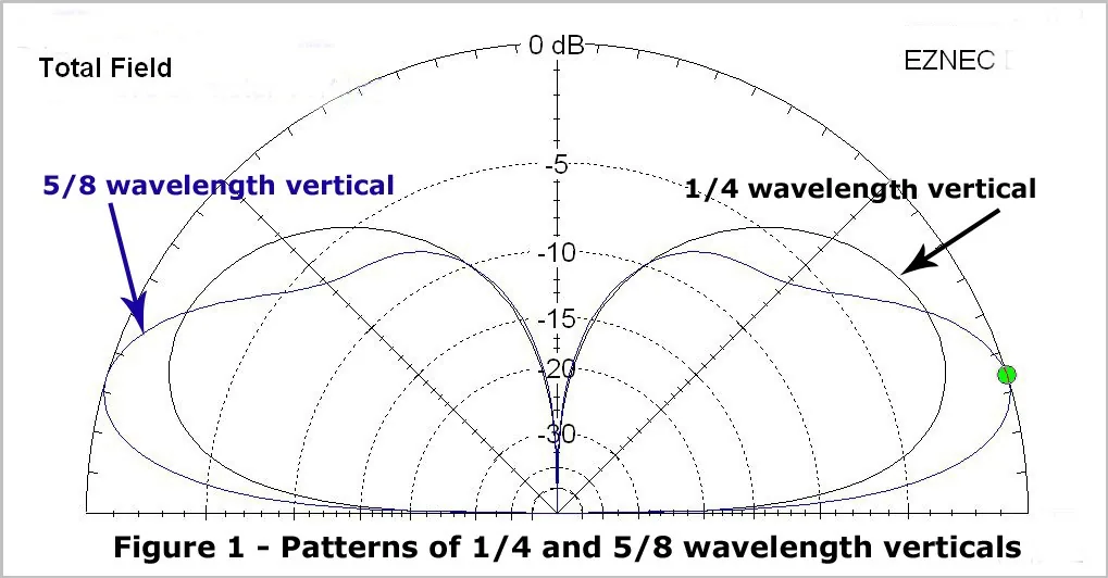
EZNEC plot: Bill Rinker, W6OAV
Figure 1 compares the radiation patterns of both 1/4 wavelength and 5/8 wavelength vertical antennas. The 5/8 wavelength vertical antenna has greater gain towards the horizon than the 1/4 wavelength vertical antenna. This gain occurs because, due to the current pattern on a 5/8 wavelength vertical antenna, more of the signal is concentrated in a narrower lobe towards the horizon.
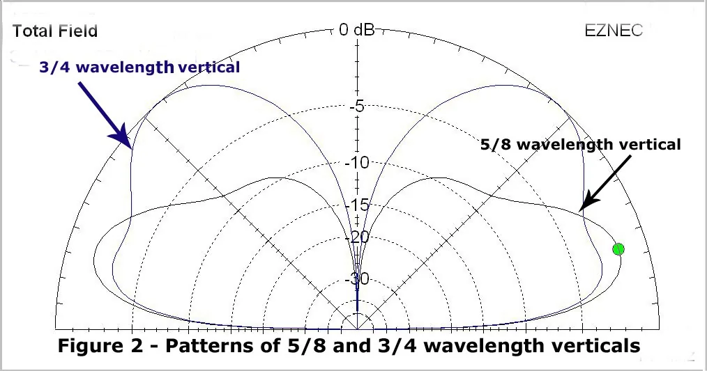
EZNEC plot: Bill Rinker, W6OAV
Increasing the length of a 5/8 wavelength vertical antenna to a 3/4 wavelength vertical antenna decreases the gain towards the horizon. Figure 2 compares the radiation patterns of both 5/8 wavelength and 3/4 wavelength vertical antennas. Most of the latter’s radiation, due to the current pattern on the antenna, is concentrated at higher angles above the horizon. This may be OK if one wants to work aircraft!
EZNEC plot: Bill Rinker, W6OAV
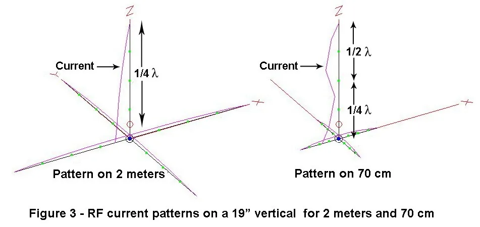
Sometimes one will hear a ham say that he can use a 2 meter 1/4 wavelength vertical antenna on both 2 meters and 70 centimeters with relatively low SWR. This is true. A 1/4 wavelength antenna can be considered as a 3/4 wavelength antenna on the third harmonic of its fundamental frequency. For example, as shown in Figure 3, a 19.1 inch vertical will look like a 1/4 wavelength antenna on 147 MHz and like a 3/4 wavelength antenna on 443 MHz. The antenna input impedance will be relatively close to the same on both frequencies. As shown in Figure 2, this is a compromise dual band antenna due to the high angle of radiation on 70 cm. However, it is an inexpensive and easy way to construct a temporary dual band antenna.
Based on the above discussion, how do the manufacturers make long dual band VHF/UHF antennas that avoid the above discussed issues? As described below, there are three basic categories of VHF/UHF dual band antennas.
Categories of Vertical VHF/UHF Dual Band Antennas
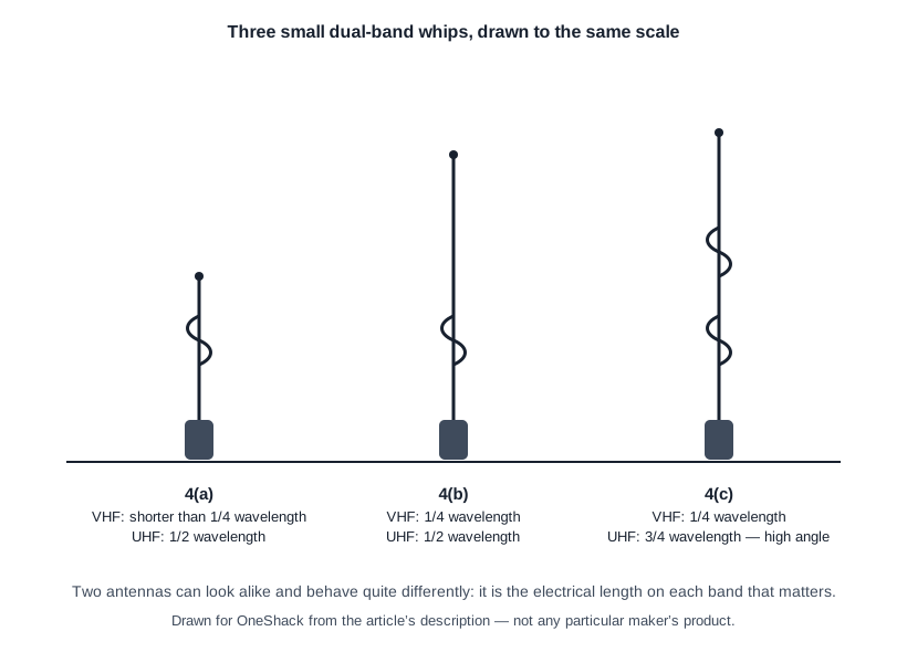
**Category 1 — antennas under 19 inches in length.** These antennas are small and provide no gain on VHF and minimal gain on UHF. Figure 4(a) shows a relatively simple 12 inch antenna that is a short loaded 1/4 wavelength antenna on VHF and an end fed 1/2 wavelength antenna on UHF. Gain specs are 0.0 dBi on VHF and 2.15 dBi on UHF.
**Category 2 — antennas approximately 19 inches in length.** This category includes simple dual band antennas that are approximately 19 inches in length. Caution must be taken with this category. Depending upon their construction, some of these antennas function as 1/4 wavelength antennas on VHF and as 1/2 wavelength antennas on UHF. Others function as 1/4 wavelength antennas on VHF and as 3/4 wavelength antennas on UHF. As discussed earlier, the latter group has a high angle of radiation on UHF. The former group has a nice low angle of radiation on UHF. Figures 4(b) and 4(c) show examples of both types of antennas.
How does one tell to which group one of these similar looking antennas belongs? Some antenna manufacturers do not indicate the configuration of these antennas. Gain figures can be deceiving. For example, one antenna of the 4(b) type is advertised as having 2.1 dBi of gain on VHF and UHF. Due to its construction, the radiation angle is about 20 degrees above the horizon for both bands. An antenna of the 4(c) type is advertised as having 2.1 dBi of gain on VHF and 3.0 dBi gain on UHF. The problem, as discussed earlier, is that the UHF angle is about 70 degrees above the horizon! A good place to find out dual band antenna configurations is a dealer that publishes the details, such as DX Engineering.
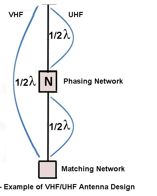
**Category 3 — antennas greater than 19 inches in length.** These antennas are usually between 27 and 50 inches and provide good low angle gain on both VHF and UHF. They are made up of phasing networks and matching networks which create collinear antennas, sometimes just on UHF and sometimes on both VHF and UHF. A collinear antenna is an array of electrical half wave dipoles in line and fed in phase to achieve gain.
How do long vertical antennas develop gain?
Drawing: Bill Rinker, W6OAV
Figure 5 shows an example of a collinear antenna and a schematic showing how low angle gain is achieved. The antenna is an end fed loaded 1/2 wavelength VHF antenna and a two half wavelength collinear UHF antenna. This 27.5 inch antenna has gain specifications of 2.15 dBi on VHF and 4.9 dBi on UHF. The phasing network provides two functions. The first function is that it acts as a loading coil at VHF to electrically lengthen the antenna since the antenna isn’t a physical 1/2 wavelength on VHF. The second function is that it reverses the phase of the UHF signal by 180 degrees as it passes through the network. Without the network, the upper half wave would be reversed and become a full wave sine wave. The matching network matches the low impedance of the coax to the high impedance of the antenna. There are many ways of designing these antennas. The longer the antenna, the more the networks and the higher the resultant gains.
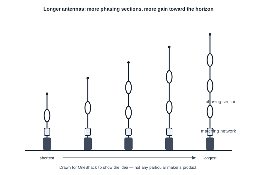
Figure 6 shows some of the various available high gain VHF/UHF antennas. Note the number of phasing networks. Some antennas have collinear 1/2 wavelength sections and some have collinear 5/8 wavelength sections. Others have a combination of both.
Analyzing Antenna Gain Figures
When analyzing antenna gain figures, verify that the figures are specified in either dBi or dBd. Gain figures such as “dB” are meaningless.
If possible, locate the manufacturer’s radiation patterns as shown in Figure 1. It’s important to know where the specified gain occurs relative to the horizon.